Plasticworks - Plastics, Fiberglass and More
Follow us on Facebook
  • Home
  • AC adapters
  • Locations
  • Products and Services
  • Covid-19 Shields
  • Gallery
  • Fiberglass
  • Links
  • Graham's Blog
  • Dennis's Blog

Bird Wars

8/16/2012

 
Bird Wars

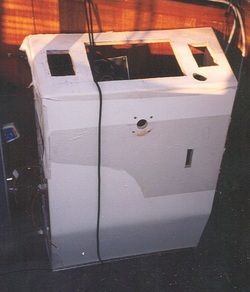
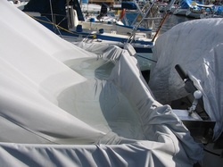
The cover on the upper deck of Morning Star is the perfect spot for sea gulls to land, have a leisurely meal of mussels, or other products of the sea, or of nearby garbage cans, and then leave their calling card. I cannot tell you how many times I have washed the cover down. A simple hosing down is ineffective in cleaning the crud off. And so I declared war on the sea gulls.

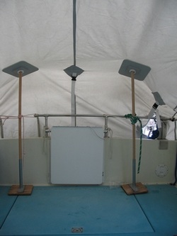
My first attempt at keeping the gulls off the cover was aluminum pie pans on cord, strung in various ways across the cover. This was not the way to go. I quickly found that to make the pie pans work I needed a spiders web of cord to hold them in the right position as they always seemed to end up just dangling over the edge. Plus the put up, take down time was excessive.

My second attempt was to make some 2” thick plastic blocks by bolting together 1/2” black Starboard. These blocks could then be attached to the 1” railing going around the top deck of the boat. Holes were then drilled into the block to receive 1/4” round fiberglass rod. The holes were drilled at angles so when the fiberglass rods were inserted they would fan out above the boat cover, preventing the sea gulls from landing. And – it worked! The rods kept the gulls off and my cover remained clean. No longer did I have to remove, roll up, and store a shitty cover whenever I took the boat out. But I was never very satisfied with this solution, which is why it never made it to this blog. While the Starboard blocks could remain on the railing all year, they did not look good, and they had to be removed for the winter cover to be put on, and they were bulky and tough to find a place to store.
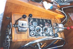
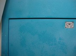
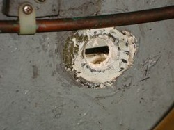
So on to my third attempt at building a better mouse trap. At some point I had discovered that the clamps on the upper rail, there to hold the bimini support frame (I have never used the bimini cover), had 1/4” holes, perfect to accept the 1/4” fiberglass rods I was using. From this discovery the current design evolved.
Picture
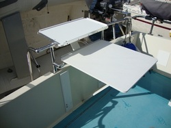
A k.i.s.s. solution.
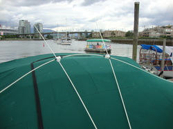
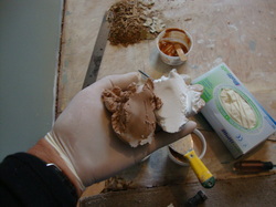
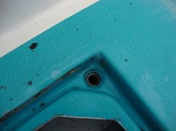
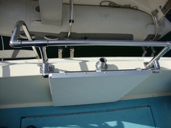
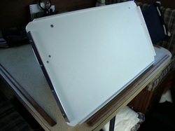
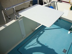
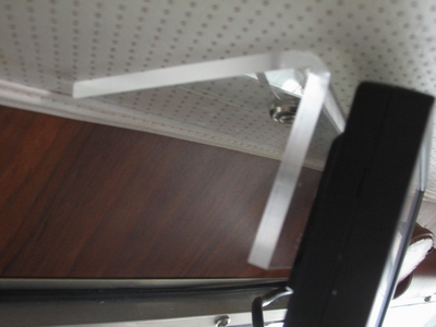
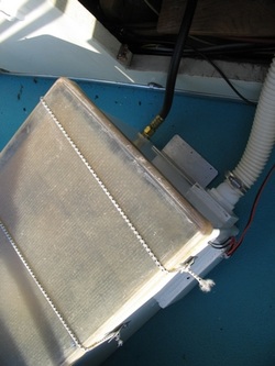
A length fiberglass rod is inserted in the unused bimini frame clamps on the upper railing. The spring in the rod holds it in place. Attached to this side to side rod, via swiveling plastic blocks, are two fore and aft rods which project above the flat sea gull landing area of the cover. The swiveling blocks allow the whole affair to be rotated so all the rods are parallel with each other, allowing for easy storage.
Picture
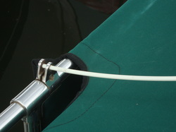
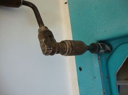
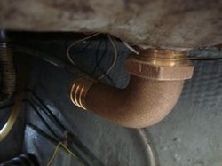
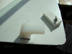
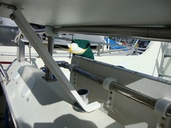
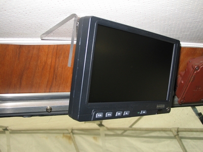
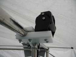
Bimini FrameClamp with side to side rod inserted in it.
Picture
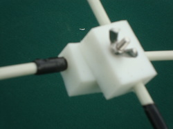
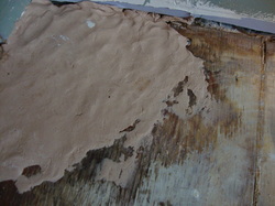
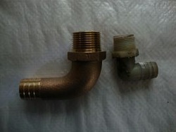
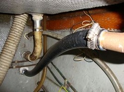
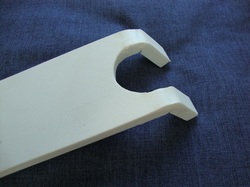
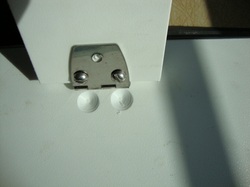
Swiveling blocks, with holes drilled that rods pass through. The black is electrical tape on the rods to position them relative to the blocks.
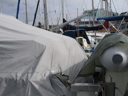
Amazingly – it works! The two rods are just as effective as the previous 6 in keeping the birds away. Even though the rear sloping part of the cover just has the rods lying on it the birds stay away. (This sloping area was never much of a problem but with the flat part of the cover protected I was concerned the gulls would migrate to the sloped area, but this has not happened.)

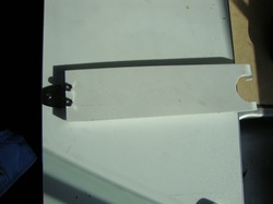
After proving up the system I did modify the side to side rod by cutting it in two, and then using a plastic block with a hole drilled in it to join the two pieces together. This shortened the overall length when taken down and folded, and made storage easier.

So come on in, grab some chunks of plastic and let your mind free range. And remember our new address Surrey Plasticworks Ltd now at 12198 86th Ave, Surrey BC.

Rot Fix During Reno's

3/31/2011

 
Reno Rot

 The latest project at our place, a bathroom reno.  Reno’s always produce something unexpected, this time it was dry rot at the hinge side of the bathroom door.  It turns out water had been coming down the furnace B vent, and then continuing downward behind the door casing until it pooled on the floor, under the carpet, never leaving a visible trace, but causing a pocket of dry rot in the plywood floor.  The floor in this area consisted of 5/8 plywood, overlain by a sub floor of 3/8 plywood.  The dry rot had consumed the 3/8 plywood but had not penetrated through the 5/8 plywood.  Plus the area of dry rot was located in an area that would not be subject to the weight of traffic, or any other stress for that matter.  Thus I felt a non structural repair would suffice.
Picture
Looks pretty ugly after a couple bangs to loosen the rotted wood.
First I scraped away the dry rot.  I was not that thorough on this, I hate working slowly, but I did get most of it.  The area removed was very irregular in shape as well as in depth.  As a first step in filling the cavity I cut a piece of 3/8 plywood roughly the shape of the cavity, but trimming it back so that it sat in the cavity but did not project above the surrounding floor level.  Next I mixed up some epoxy, I used Cold Cure, and thickened it with wood flour.  I could just as easily have thickened the epoxy with cab o sil or glass bubbles or micro fibers, but wood flour was what I had at hand.  I then spread the thickened epoxy in the bottom of the cavity and pressed in the 3/8 cut to shape plywood, additionally secured with screws.
Picture
The cavity cleaned of rot, thickened epoxy ready to go in.
Picture
Plywood set into the thickened epoxy, and held in place with screws.
The next step is to fill the cavity up to the level of the surrounding floor.  PlasticWorks sells a product called SculptWood, made by System Three Resins, the same company that makes Cold Cure.  SculptWood is a two part epoxy putty with a mixing ratio of 1:1.  Because the material is so thick I could not think of an easy way of measuring the parts to get an equal amount of each.  So, I just scooped out a ball of part A, and by eye scooped out a matching ball of part B.  By hand, using rubber gloves, I kneaded and mushed the two parts together until I had a uniform consistent colour.  In my first attempt to apply this mixture to the cavity and to cover the 3/8 plywood I used a metal spatula, a wide putty knife.  It did not work.  As soon as the spatula passed over an area the SculptWood underneath would lift up and curl back toward the top of the spatula.  I abandoned the spatula and resorted to using my hands to press the SculptWood into the cavity and on to the plywood, using a straight edge, my level, to check that the SculptWood had filled the cavity to approximately the level of the surrounding floor.  Since the floor was to be finished with ceramic tile I felt the thick mortar under the tile would make further leveling unnecessary. 
Picture
SculptWood
Picture
Part A and part B ready to be mixed. The spatula is in the background.
Picture
The finished repair, ready for ceramic tile.
So the job was complete, a good time to now read the SculptWood directions!  And I found that it is recommended that SculptWood be pressed in place and rough shaped by hand.  Once the material has hardened it can be brought to its final shape using regular wood tools, rasp, chisel etc.
 
Because of the way the SculptWood had peeled off the plywood when I applied it with the spatula I was concerned about how well this material would adhere to the plywood.  Thus, as a test, I pressed a lump of SculptWood onto a scrap of plywood and let it set. My concerns were unfounded, the lump of SculptWood could not be removed from the plywood!
 
All in all I was quite pleased with the way this repair went and I am confidant that the Cold Cure, plywood, SculptWood repair will last as long as the house will.

A project from the past: New Console

3/18/2011

 
New Console  

This is reaching back in time to my previous boat, a 36 ft. trawler. This was an older boat, and while it had received good care over the years parts of it were dated or just plain tired. This was my diagnosis of the lower station console. I wanted a fresh look rather than any change in function. I resolved to build a new console. The console held the engine controls, engine gauges, steering wheel, various other controls and gauges and AC and DC fuse panels.   
Picture
The original console, fully functional but dated and lacking any snap.
There really was not the option of changing the size or shape or funtion of the console. It was a question of duplicating it in fiberglass. If you look back, I have an entry discussing reworking the propane system of my existing boat and the method of making a mold. I used the same technique here. I created a female mold of melamine particle board, where the inside of the mold duplicated the outside of the control console. This was a very easy 4 piece mold. Next I used a bondo type product to round the corners inside the mold. That completed the mold. Next I painted the inside of the mold with 2 layers of white gel coat, and once that had cured began laying up fiberglass. I laid in 1 oz mat, followed by 18 oz roving and did this twice (maybe 3 times, I kept no notes). The new fiberglass console was then removed from the mold, trimmed, bondo that pulled away from the mold removed, and the entire unit sanded ready for painting. As an aside here, I get a lot of people working on a project like this who want the gel coat to be the finished surface. It is just not worth the effort. Your mold must be flawless, and for a one off it is just not worth the effort. Further your skill levels are probably just not up to it. To be a fiberglass mold maker requires skills built up over an extended time with much trial and error. There is a reason fiberglass molds are expense and a reason mold makers are reluctant to share the knowledge they have painfully accumulated. Go the paint route and save yourself a lot of heartache. We all know how to sand.   
Picture
This is the new console set in place. Holes have been cut for steering, controls and gauges. Top has been masked off to prevent scratching during insulation.
Once the fiberglass console was complete, but before the holes were cut, I attached plywood panels to the inside to the console. The plywood was not fitted to be seamless, it was just 4 pieces of plywood cut to shape, pushed close together, and attached to the inside of the console with thickened epoxy. The fiberglass looks thick in the above picture because of the plywood backing on the inside. The plywood backing was necessary to hold screws from the outside, and more importantly to allow easy anchoring of wires, cables etc on the inside.   
Picture
This is the birds nest of wiring and cables that was contained in the console, all had to be sorted out and laid out in some way on the bulkhead or the inside of the console. The heavy cables to the right are the hydraulic steering cables, but I cannot even see the engine controls in this chaos. I love this picture.
Picture
Here is the new console in place and pretty well finished. There is a piano hinge at the bottom that allows the console to fold flat to the floor, so you have reasonable access for all the wiring work.
Picture
New AC and DC electrical panels on the port side of the new console.
Picture
The console finished, fully functional, and dressed up with a matching foot rest. Upholstery of the captain’s chair was changed from white to black, keeping the white clean drove me to drink. Note plexi GPS holder to right, ABS binoculars holder to left, and dark smoked acrylic sliding doors to storage area at bottom. All with material from PlasticWorks. Come see us!


Was it worth it? I think so. The salon certainly looked more modern, and all the old fuses had been upgraded to circuit breakers. And do not underestimate the satisfaction you will get every time you look at a completed project like this. I feel good just reliving it all as I write this.   

A project from the past: The cover up.

3/18/2011

 
 I came across some pictures of my previous boat, an older 36 ft. trawler. When you sat in the salon and looked across to the cabin entry door you were staring at a big ugly stain in the wood paneling at the corner of the door. The leak problem that caused the stain had long ago been solved, but the stain remained. I spent a long time staring at that stain and plotting how to get rid of it. This is what I ended up doing.

 Using 1/8 white ABS I fashioned a plate to cover the stain, including going around the door trim at the bottom. To this plate I then attached a 3 sided box, sized to fit a flashlight. The unit was then fastened to the wall covering the stain. Since the unit had a purpose, to hold the flashlight, it was not obvious that its real purpose was to cover the stain.

New Deck Drains

6/15/2010

 
This project does not involve any materials or services from PlasticWorks but it does deal with fiberglass.

The rear deck of my boat has 2 large hatches. Inset at the edge of each hatch is a gutter or trough that handles any rain or wash water. In the gutter of each hatch are 2 drains that take the water from the gutter, through a hose, and out via a through hull installed above the water line. The problem is that these drains are small, make a right angle immediately below the deck, and plug very easily with sea gull crud that I seem to get more than my share of. As a result I get a lot of rain water that ends up in the bilge. There is a very active web site for Tollycraft owners so I went there to state my problem and seek advice or comments about reworking the drains. What comments I got were very negative, basically that I was entering into unknown territory, no one seemed to have tackled this problem. So for a year I set the problem aside and went on to other projects.
Picture
Deck hatch fits into drain gutter.
Picture
The original drain - hatch cover removed
This fall I put on the winter cover, which of course eliminates the problem because no rain or sea gull crud gets on the deck. However the winter cover also allows me to work under cover, so lets take a run at this problem. I had lots of paper schemes that went no where, I tried to fabricate some small fiberglass drains with a 90 degree bend but the hose connection never turned out right and I never did try and install them. Eventually I settled on a bronze fitting, threaded on one end and sized for a 1″ hose on the other end. My plan was to wax up the threads and cast a fiberglass plug. The fitting could be twisted out and the plug glassed in place under the deck then the fitting reinstalled. However before I could act on this plan I came across a reasonably priced tap, so why not try and tap directly into the deck? Even if it did not work I could go back to my original plan.
Picture
The new drain fitting and the original one.
Picture
The tools: hand brace with twist drill, the tap and battery drill with step bit for enlarging hole for through hull.
The original drains were twisted out (were they tapped in when the boat was built or was some other technique used?). The tap called for a 1- 5/32 ” hole, but the only reasonable readily available bit I could put my hands on was 1-3/16″ so I would go with that. I was aware that taking a big hole (the existing one) and trying to make it bigger using a twist bit would probably lead to a three sided hole; I had just had this problem recently while trying to enlarge a hole in some plastic. My plan was to drill the hole by hand and eliminate the chatter a battery or power drill would create. I rigged the bit in a hand brace and proceeded to enlarge the hole. The bit had to be backed up frequently to keep it from biting in too much, and downward pressure was minimal, but in a few minutes I had a new, enlarged, perfectly round hole.
Picture
Widening a hole with a twist drill can result in chatter, leading to a three sided hole, as happened in this other project.
Picture
Using the hand brace to widen the hole I hoped to get a round hole that I could use the tap on.
Next to tap the hole. The fiberglass deck at the location of the hole was reasonably thick, and this helped the tap start easily. The tap was turned with a wrench, with as much downward pressure as my other hand could muster. Turning the tap required a lot of muscle, however the tap did seem to be cutting the fiberglass as opposed to pushing it aside and forcing its way in. At this point I was committed, if the deck cracked I would deal with that later. It was going so well I forgot to get a picture of the tap in action.
Picture
I now have a threaded hole in the deck, ready for the new drain.
The new bronze drains turned in easily, but did require quite a bit of force to get them up to the top of the deck. I am not certain this technique would have worked if I had started with the 1-5/32″ hole recommended. I put a bit of caulking on the threads when I was screwing them in and a bit more on the underside of the deck. I will check them later and may put more caulking on the underside when the weather warms up.
Picture
New drain screwed in place.
Picture
New drain from below deck.
Next was to replace the existing through hulls with new ones sized for the 1″ hose. The through hulls were reasonably accessible and did not require more than the normal amount of contorting and positioning yourself in unnatural positions. The visible caulking was scraped away and the backing plates screwed off and the old through hulls pushed out. The holes in the sides of the hull were enlarged using a step bit and a battery drill, working from the dock on one side and from the dingy on the other side. New through hulls were then installed, and 1″ I.D. hose connected to the new drains and the new through hulls.
Picture
Original through hull removed. Hole was enlarged with step bit working from the outside.
Picture
The new drain, with hose connecting to the new through hull. (Reminder, must clean or replaces some of those other hoses.)
For the new system the most restrictive point is the I.D. of the through hull at .75 inches. The I.D. of the old through hull was .45 inches. Thus the new system produces a cross sectional area of .44 sq. inches, as compared to the original of .16 sq. inches, an almost 3 fold increase, and the sharp right angle bends are replaced with the sweeping curve of the bronze units.

This was one of those projects where everything went right the first time. We need that every once in a while don’t we? Maybe the next project will go the same way.

Rail Mounted Tray

11/12/2009

 
I wrote earlier about the fold down table made for the rear deck area. The table works fine, always available and out of the way when not in use. However it is not very big. Thus when Patricia does a full meal there is not enough room for everything on the table. The table cannot be made larger without making it much less convenient, or at least I could not figure out a way to make it larger and convenient. (By the way isn’t working on problems like this one of the fun aspects of boating.)

Eventually I began working on the design for a small – call it a holding tray- that would be attached to the side railing and hang mostly overboard. I envisioned the tray being used more for snacks than meals, and hanging it overboard would maximize space for deck chairs when guests are on board.

A tray was made of 1/2″ Starboard with aluminum fiddles around the outside edge. The shop CNC’d some units from 1″ UHMW to attach the tray to the rail. Next was the support to keep the tray level. Using stainless steel rod I fashioned some supports that were attached to the underside of the tray and rested on the fiberglass walls of the aft deck. It did not work. Nor did the second configuration or the third or the fourth.

Picture
This is the rail where I first tried to mount the tray.
Picture
The tray.
Picture
The original rail clips and locking tabs could still be used, it was the support system that did not work, leaving many unused holes in the underside of the tray.

 ”Patricia, you will have to live with what you have.” At which point she started using the boarding step to handle the overflow of dishes. It worked during the 3 weeks of cruising we got in this year, but…

 Then, sitting at the table one day I started looking at the unused flag holder attached to the top of the fiberglass railing. Perhaps I could use the rear rail, along with a folding leg down to the flag holder to prop the table level. The table was already made, with the railing attachments, and a leg could be fashioned from Starboard. The Starboard would need to be bent, something I had never tried before. 

After my previous failures I could not wait to get to the shop so I would work with the tools I had available. The leg was cut to size. Leaving lots of extra length as the final fitting would be through trial and error. The U shaped cut was made using a jig saw, at the point of the bend the Starboard was cut part way through with a hand saw and then V’d out using a wood chisel. Starboard is great to work with. I had never worked on it with a chisel, but the V was cut easily with just hand force. The piece was then put in a vice, heated with a hot air gun, and bent by hand. It bent easily, but there was a lot of spring back so it was held in place until it cooled. It cools slowly! I cleaned up all the saw cut edges with a fine rasp. It went quickly and finished smoothly. As I said earlier, great stuff to work with.
Picture
The top rail that I would mount the tray to, the flag holder, and the new rail and table previously installed.
Picture
The existing table and support leg. The support leg had never been a problem.
Picture
The Starboard support leg, shaped and bent.
Down to the boat to attach the leg to the tray using a stainless steel hinge. The leg had to be cut a few times to get the length that would keep the tray level. And - it works!
Picture
The completed tray in place, a step up from the table.
Picture
Support leg wraps around the flag holder.
While the table can be left permanently in place, the tray cannot and will have to be stored when not in use. One last problem. The heads of the bolts holding the leg to the hinge prevented the leg from folding flat against the table. I had a large drill bit on board and thought I would try and drill some shallow holes that the bolt heads would drop into. I was concerned that the grabby nature of all plastics like Starboard would pull the drill right through the tray. However with slow speed on the battery drill, and withdrawing the drill every few turns all went well.
Picture
Divots, to allow leg to fold flat.
Picture
Leg folds flat against underside of tray.
 ”Patricia, you should sew a case for your tray so when we stow it nothing gets scratched.”

- Dennis

Winter Cover

3/30/2009

 
Winter Cover Supports

I have a full winter cover for my boat. The high point is at the helmsman seat on the upper deck and from there it slopes down to the rear rail and then down to a cinching strap at the level of the swim grid.

The problem is right at the rear rail. The fabric sags a bit, the water collects a bit, which cause it to sag some more, so it collects more water etc. It very quickly collects a huge amount of water, probably approaching 100 lbs. (Say the equivalent of a 20 liter pail on each side which would be 88 lbs.)
Picture
To overcome this problem I made some pads of 1/2″ Starboard, a marine plastic. On the underside of the pads I attached plastic donuts of a thicker material, the supporting rods would go into these donuts. The donut holes were made larger than the supporting rods so the Starboard pads could pivot and take the slope of the cover.
The bases were welded and screwed to pieces of plywood. Under the plywood I put some expanded rubber, the type that is used on boats to keep the plates from sliding off the table. However even this was not enough to keep them from sliding, and thus the upright supports had to be tied in place so the cover would drain properly.
Picture
Picture
Problem solved. No more ponding water.

Rearview Camera

3/30/2009

 
Rear View Camera

Pretty hard to make a case for this indulgence. Call it redundancy, always a good strategy where boats are concerned.
When steering from below, which I do frequently, as soon as it gets a bit rough, I cannot see behind the boat from where I sit to steer. The dingy mounted on the swim grid blocks my view. Thus to get a look behind I have to leave the wheel and go on deck to get a look over the dingy. Then the boat would get off course, quite quickly if it was a little rough, thus the auto pilot was added. However applying the principle of redundancy the camera will eliminate the necessity of going on deck, however if I do have to go on deck I have the auto helm.

I had actually played around with some rearview mirror ideas, none of which worked. Then I came across an article on rear view cameras in DIY Boat Owner magazine.

These cameras are made for RV’s, buses, and vehicles in general so I knew there would be some issues during the install. The magazine article was well researched so I felt confident going with their recommendations. My email with the few questions I had was quickly answered, another good sign. (www.rearviewcamera.net)

The monitor mount that came with the kit was made for vehicles. A ceiling mount of 1/4″ Plexiglas was easily fabricated, attached to the ceiling, and the monitor attached to the mount. No trick here, but doing things like this in plastic sure makes it easy.
The outside camera mount involved a little more work. The kit came with a camera mount to go on a flat surface. A platform for the camera mount was fabricated, that would then attach to the rear rail of the upper deck. The cord from the camera would go into the cabin through a hole drilled in the cabin wall. However the cord from the camera is not very long and if the camera was mounted on top of the rail it was very tight to get it through the hole. Thus I opted for a lowered platform design, which lowered the camera by about 1″, but this was all I needed. For the platform I used 1/2″and 3/4″ cutting board material because that was handy, but I could have used UHMW or Starboard. The upper and lower pieces were grooved out to take the 1″ railing, and then bolted together and then the camera mount attached to the platform. 

Again this was a very easy fabrication. The trick is to think of plastic as an option for dealing with these situations. Drop in and see us!
Picture
Picture

Auto Pilot

12/22/2008

 
Based on last summers cruising, which I did alone, I felt an autopilot would be a handy addition to Morning Star.
I will spare you all the planning - where to locate the flux gate compass, how to tie the rudder sensor to the rudder arm, and all the work of stringing wires through already overcrowded conduit, and move on to the parts where I made use of PlasticWorks.

The wire sizes, to avoid voltage drop, were very large, 8 ga. These wires were too large to attach to the course computer and I had to install a short length of 10 ga between the course computer and the 8 ga. These are still very stiff wires that could not be tucked out of sight without pulling them loose from the computer. It looked terrible…
Picture
The plastic solution was to have PlasticWorks make a simple bent cover of black .060 ABS that projected below the computer and covered the wires. The cover extends a long ways under the mounting shelf so anything slid underneath will not pull the wires from the computer.
Picture
Picture
I wanted to mount the autopilot controller to the ceiling of the cabin. This would make it visible from the helm yet far enough away from the radio and compass to not effect them. A simple Plexiglas bracket was the answer. The installation instructions had a mounting template, fully dimensioned, so the bracket was CNC cut for the holes needed and then bent to the viewing angle I needed.
Picture
I also had to string the wire from the controller to the course computer. This is the wire running to the right of the controller, along the aluminum window frame, with no visible means of support. To keep the wire tight to the aluminum frame I used a dab of E6000 adhesive behind the wire and held it in place with masking tape until the glue set up. I was very pleased with how this worked out.
Picture
The wire does not show up well in this picture, but it is not going anywhere. E6000 adhesive is available at PlasticWorks. We use it regularly in our shop for dissimilar materials, such as acrylic to metal.

Propane Box

12/18/2007

 
Propane Box

Warning: What follows is a description of what I did. It is not a recommendation, has never been inspected, may not be legal or meet any required codes.

This was an early project, but one of the most involved.

Morning Star has a propane stove. The tank was located under the console of the upper bridge deck. The tank was old and rusty and not fastened down. As well, over time holes had been drilled from below to route wires for radios, antenna cables and miscellaneous other add ons. Propane is heavier than air. Thus any leaks in the vicinity of the tank could find their way into the cabin.

I was going to correct these problems by putting a new tank in a sealed box with a vent line so that any escaping gas would be vented over board. It sounds simple but there were many little problems to be solved along the way.

The box and the tank. While there is lots of space under the console the door into it is of limited size. Also the front to back distance is limited, so any size box would have to go in with a twist so it sat at an angle to the fore aft line of the boat. A regular propane tank would not work. After much searching I found a very expensive aluminum horizontal tank that would fit the box size limitations. The final size of the box was now worked out. The box had to contain the tank, regulator, pressure gauge, solenoid, and allow for the propane to exit the box to the stove in a non leaking manner and for any propane within the box to be vented over board. The box would have a shoe box type lid, with a gasket, held on with bungee cords. 

A female mold was constructed using melamine, the corners filleted with body filler, and then the fiberglass was laid in. Lay up consisted of 1.5 oz mat, 18 oz roving and 1.5 oz mat. The mold was then taken apart to remove the fiberglass box. 

The filleting I had done was pretty rough so the corners were cleaned up and filled and smoothed. No one was going to see the box so I was not very concerned with appearance. Plywood strips were cut to hold the tank in place and Sikaflex was used to attach these to the bottom of the fiberglass box. Sikaflex was also used to attach plywood at one end of the box so the regulator could be attached without having bolts going through the box. The box was then drilled so a brass fitting could be inserted, sealed from both sides, the hose from the regulator attached at the inside and the outside connected via a flexible line to the line that ran to the stove. A second larger hole was drilled, a through hull fitting was installed, sealed from both sides, and a large hose attached outside the box and lead to an existing vent at the leading edge of the console. Single sided foam tape was used as a gasket on the inside of the lid.
Picture
On the left the propane line going to the boat system, the large through hull fitting and hose to take any leaking propane over board, oh yes and the electrical lines leading to the solenoid. Bungee cords holding down the lid.
The ins and outs of things:

 It became apparent during the above process that the only way to get the tank in and out of the box was while it was outside the console. Thus the supply and vent hoses had to be long enough for the box to be taken out from under the console without having to remove them each time. Taking the box from under the console onto the deck so you could check the tank or remove it for refilling was difficult, you had limited leverage to lift it, were working on your knees in a tight space etc. 

To make this easier I used some cut to size 2×4′s and plywood to raise the area where the box sat so that it could be slid out rather than having to be lifted out. To lock the box in place I attached aluminum angle to two sides of the box, with slots cut in the aluminum so hold downs could go through the slots and into threaded inserts set in the plywood. The aluminum was attached to the fiberglass box with Sikaflex. (Just an aside here. I have had Sikaflex affect some paint so that the Sikaflex and the paint just peel away from the substrate. My rule now is to apply Sikaflex only to gel coat or raw fiberglass.)

Picture
Box going in. It is a tight fit and at this point the box must start its twist to the left. Note aluminum hold down brackets.
Picture
Box in place and locked down to the raised plywood shelf. The red and gold lines on the left are the control cables for speed and shifting. The white block of UHMW behind them protects them from being cut by the aluminum hold down when the box is going in and out. That is how tight this installation is.
Picture
Under the upper console the vent hose from the propane box leads to an already installed vent. Any leaking propane will vent out above the front windows.
Picture
The box lid with the sealing gasket.
The verdict. 

With a new tank, and all new fittings the chances of leaks are minimal. However I am quite convinced the set up will function as intended. The weakest point is probably the connection between the flexible hose leaving the box and the copper line that runs through the boat. I just have to be careful when removing the box that I do not pull it out too far and put stress on this joint. The foam tape used as a gasket in the lid seems to provide a good seal all around the edge of the box. The aluminum angle hold down system has survived some rough crossings and appears adequate to the job, and is fairly easy to position. 

Yes the lid should be painted and also the plywood shelf, but I was so tired of this project by the time I finished I just closed the door and went cruising.

- Dennis Facer
<<Previous
Forward>>

    About Dennis

    Dennis Facer is the father of Greg and Graham Facer (who run Plasticworks).  He is occasionally retired but loves to spend time working on this or that.  You can often see his projects or the results out at the shops.

    These are some of his projects.

    Archives

    July 2023
    March 2023
    December 2013
    September 2013
    June 2013
    August 2012
    March 2011
    June 2010
    November 2009
    March 2009
    December 2008
    December 2007
    November 2007
    July 2007
    June 2007
    February 2006

    Categories

    All

    RSS Feed

Need it Shipped?

We ship sheet goods and fabricated products all over the lower mainland and southern BC.  As well, we ship our brochure holders and Velcro® Brand products all over Canada.  If you can't make it in, give us a call and we'll work out a great shipping price to get what you need to you when you need it.